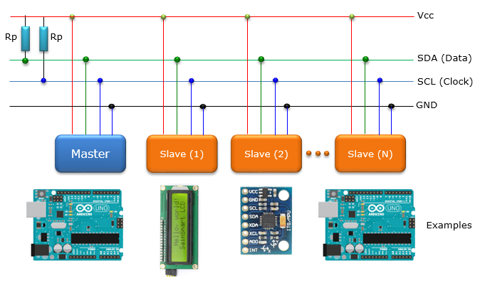

Generally, one card will send information (Writer) and another will receive it (Reader). In order for the two cards to communicate with each other, they must be connected correctly (A4 with A4 and A5 with A5) and do not forget to connect the earths (GND) as shown in the following diagram.Ĭaution: If pins A4 and A5 are connected to the pins of a non-powered card, the code will freeze at the time of transmission. In this example we use an Arduino Uno board, so the pins A4 and A5. One on which the data is sent (SDA Serial Data Line) and on the other the synchronization clock (SLC Serial Clock Line). The pins used by I2C communication are usually fixed for each device. For that, we have to write at least two programs, one for the “Mistress” card (Master) and the other for the “Slaves” cards.Īn I2C communication is defined by a two-wire bus (sometimes called TWI, Two Wire Interface) and an address. An interesting example is the communication between several Arduino boards. With the I2C protocol, it is also possible to communicate between different systems (sensors, LCD screen, Raspberry Pi, etc.).


It allows asynchronous connections between several components to share information via a “common bus”. The I2C protocol is a method which makes it possible to connect several “Master” cards and several “Slave” cards and to communicate up to 128 devices. One of the commonly used techniques is the I2C (or TWI) protocol. It can be practical, especially in home automation projects, to communicate between several devices.


 0 kommentar(er)
